ATmega328P Datasheet
In this eighth assignment, we are introduced to embedded programming. After reading the Arduino ATmega328P datasheet I understood that it is present on the Arduino UNO board but also on other similar models such as Arduino Funduino UNO. It has 14 digital inputs and outputs, of which 6 can be used as PWM, it also has 6 analog inputs, it runs with a 16 Mhz resonator, it has a USB connection, a jack for external power, an ICSP connector and a reset button.https://eu.mouser.com/datasheet/2/268/Atmel-8271-8-bit-AVR-Microcontroller-ATmega48A-48P-1315288.pdf
http://ww1.microchip.com/downloads/en/DeviceDoc/ATmega48A-PA-88A-PA-168A-PA-328-P-DS-DS40002061A.pdf
 Arduino pinout diagram.
Features
· Microcontroller: ATmega328· Operation voltage: 5V
· Input voltage: 7 - 12V
· Input voltage range: 6-20V
· Digital I / O pins: 14 (6 PWM)
· ADC: 6
· Current per I / O pin: 40mA
· Flash memory: 32KB (0.5 KB used in bootloader)
· SRMA: 2KB
· EEPROM: 1KB
· Clock: 16Mhz
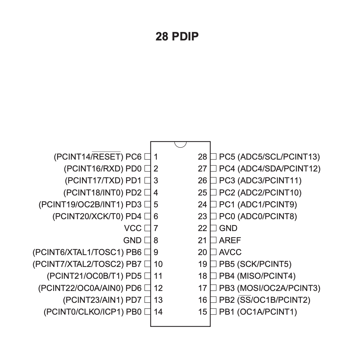
PIN Descriptions
· VCC = digital supply voltage.· GND = ground.
· Port B = 8-bit bi-directional I/O port with internal pull-up resistors (selected for each bit).
· Port C = 7-bit bi-directional I/O port with internal pull-up resistors (selected for each bit).
· PC6/RESET = if the RSTDISBL Fuse is programmed, PC6 is used as an I/O pin. Note that the electrical characteristics of PC6 differ from those of the other pins of Port C.
· Port D = 8-bit bi-directional I/O port with internal pull-up resistors (selected for each bit).
· AVcc = supply voltage pin for the A/D Converter, PC3:0, and ADC7:6. It should be externally connected to VCC, even if the ADC is not used.
· AREF = analog reference pin for the A/D Converter.
· ADC7:6 = TQFP and QFN/MLF package, ADC7:6 serve as analog inputs to the A/D converter. These pins are powered from the analog supply and serve as 10-bit ADC channels.
Programming a LED with analog/digital write
I started testing to operate the led with a button and a potentiometer that I have in the Keyestudio kit. In the case of the button it is programmed with “digital write” since the information is 0 or 1 (false or true). In the case of the potentiometer, it is programmed with “analog write” since the information comprises a range of values between 0 and 255. I have been looking at the following tutorials to get started:Testing the Tutorials
LED (Digital Write)
https://video.keyestudio.com/KS0083/LED + Push Button (Digital Write)
https://wiki.keyestudio.com/index.php/Ks0083_keyestudio_New_sensor_kit_with_Uno#Project_9:_Digital_Push_ButtonLED + Potentiometer (Analog Write)
https://www.arduino.cc/reference/en/language/functions/analog-io/analogwrite/https://wiki.keyestudio.com/index.php/Ks0083_keyestudio_New_sensor_kit_with_Uno#Project_26:_Analog_Rotation_Sensor
LED + Capacitive Sensor (Analog Write)
https://wiki.keyestudio.com/index.php/Ks0083_keyestudio_New_sensor_kit_with_Uno#Project_10:_Capacitive_Touch_SensorHere you can find the files:
11_LED.ino
11_LED+PushButton.ino
11_LED+Potentiometer.ino
11_LED+Capacitor.ino
Faculty
Future Learning Unit Team
Year
25/3/2020
Category
Fab Academy